SMT Equipment for Sale Guide to Buying Used, Refurbished, and Affordable Machines
Introduction In the competitive world of electronics manufacturing, selecting the right Surface Mount Technology (SMT) equipment is critical to optimizing […]

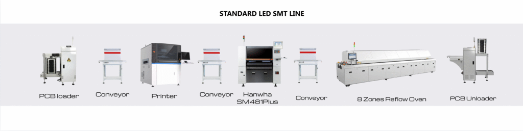
SMT Lines are production lines for PCB assembly. Various Types of smt lines are Automatic SMT Line, High Speed PCB Mounting Line, LED, and LED Lens Assembly Line. These Lines cam be very simple or very complex it depends on the end product assembly requirements.
Introduction In the competitive world of electronics manufacturing, selecting the right Surface Mount Technology (SMT) equipment is critical to optimizing […]
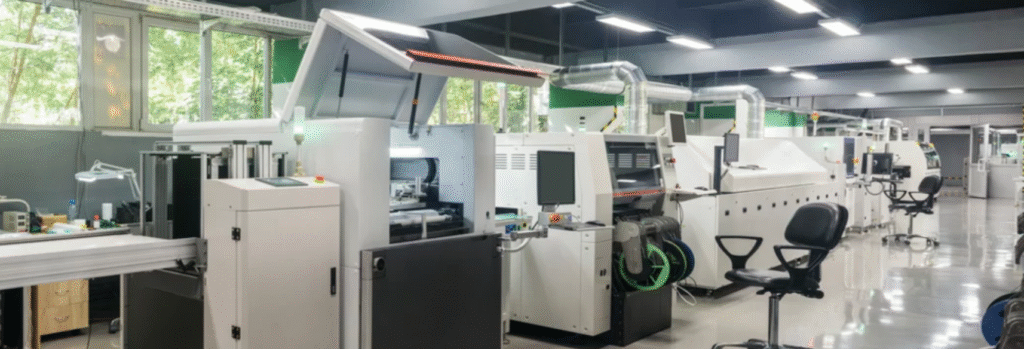
In the world of modern electronics manufacturing, surface-mount technology (SMT) is crucial for achieving high-speed production and high-quality printed circuit
What Is an Automatic SMT Line? Complete Beginner’s Guide to SMT Production Lines, Machines, and Manufacturing Benefits In today’s electronics