SMT Equipment for Sale Guide to Buying Used, Refurbished, and Affordable Machines
Introduction In the competitive world of electronics manufacturing, selecting the right Surface Mount Technology (SMT) equipment is critical to optimizing
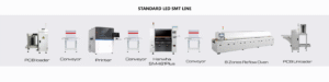
SMT Lines
Comprehensive Guide to SMT Line for Production
In the world of modern electronics manufacturing, surface-mount technology (SMT) is crucial for achieving high-speed production and high-quality printed circuit
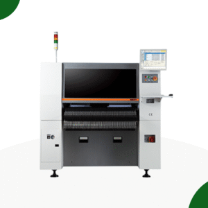
SMT Pick and Place
What is Pick and Place Machine?
A pick-and-place machine is an automated robot primarily used for picking up components and placing them in a specific location.
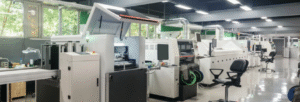
SMT Lines
What is an Automatic SMT LINE?
What Is an Automatic SMT Line? Complete Beginner’s Guide to SMT Production Lines, Machines, and Manufacturing Benefits In today’s electronics