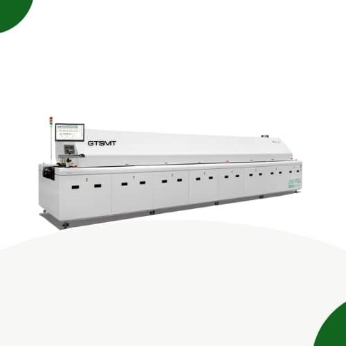
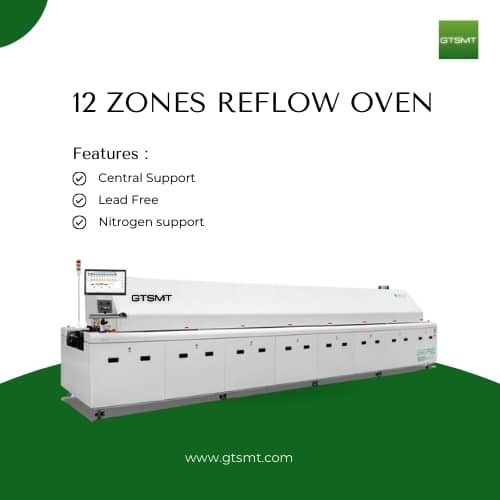
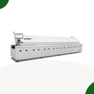
Reflow oven machine 12 zones GT-R12
CORE TECHNOLOGY AND ADVANTAGES
Long effective heating zone in the industry, with reasonable distribution from top to bottom, uniform and sufficient heat conduction, greatly improving heating efficiency, Adopting customized heating wire from GTSMT, it has high heating efficiency and long service life.
Imported Hardware for smt reflow oven machine
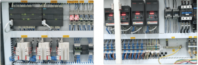
The control system adopted with Siemens PLC & modular circuit to stabilize and accurately repeat precision
Adopted foreign famous brand material as its major parts, which has guaranteed durability and reliability.
Conveyor with well parallel and transmission is stable

The rail is dealt with the hardened process to make it more stable. Segment design that can release the pressure makes the guide rail more durable, not easy to bend and deform also not drop the board.
Mesh belt and chain transmission
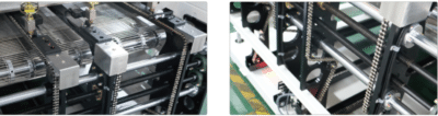
The conveyor system adopts both a mesh belt and a chain, which is suitable for the efficient production of various products.
The chain adopts the automatic tensioning design to ensure that the long-term use is not loose and the board will not drop.
Simple operation management
The Windows 10 operating system English interface on-screen alternative is available. The intelligent diagnosis system has the functions of Trouble Remind, Alarm list-out, and Report Saving. All production data will be backed up automatically and easily for lS0 9000 management.
SMT Reflow Oven 12 zones Specifications
| Category | Item | GT-R12 Reflow Oven |
| System | Dimension (L×W×H) mm | 7290×1426×1560 |
| Exhaust Volume | 10m³/min×2 channels | |
| Size and Power | Startup Power | 38KW/40KW-N2 |
| Normal Power Consumption | 13–14.5KW | |
| No. of Heating Zones (Top/Bottom) | Top 12 / Bottom 12 | |
| Length of Heating Zone | 4720mm | |
| Warming Time | ~25 min (Approx. 25min) | |
| Heating System | Temperature Setting Range | Room temperature–300°C |
| Temperature Control Type | PID closed-loop control, SSR driven | |
| Temperature Control Precision | ±1°C | |
| Max. Temperature Difference in Temperature Zones | Max. 40°C | |
| Preheat Temperature Difference Between PCB Edges | Max. 8°C | |
| Temperature Elevation on PCB | ±1.5°C | |
| Cooling System | No. of Cooling Zones | 3 |
| Length of Cooling Zone | 1200mm | |
| Rail Structure | Integral segmented | |
| Conveyor Width | 50–700mm Dual: 50–280mm | |
| Transport System | Conveyor Height | 900±2mm |
| Conveyor Speed | 300–2000mm/min | |
| Fixed Rail Side | Single Line: Front rail fixed (Rear rail fixed optional) Dual Line: 1–4 fixed or 2–3 fixed options | |
| N₂ System | N₂ Consumption | Option: Single Line 18–20m³/h or 300–1000PPM Dual Line: 25–30m³/h or 300–1000PPM |
| Electrical Configuration System | Power Supply | Same as left column |
| UPS System | Standard Configuration | |
| Alarm Display | By sound and light (e.g., over-temp, abnormal flux levels) | |
| FLUX Service Reminder | The software prompts maintenance cycle | |
| Data Storage | Process Data and Status Storage Unlimited |
Reviews
There are no reviews yet.